CSCI 210: Lab 5
7-Segment
LED
Due:
10:00
PM
on
Monday,
April 5th
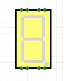
In this assignment, you will design a combinational logic circuit that takes in 4 inputs representing a 4 bit number, and display the hexadecimal digits that representing that number on a 7-segment LED display, which looks like this:
Preliminaries
We will be using the Circuitverse website to complete this assignment. You should have received an email inviting you to the CSCI 210 Sp 24 group on Circuitverse.org. If you did not, please use this link to join the group. To start the assignment, click on your name on the upper righthand side of the website. Go to "My Groups" and you should see "Lab 5" under assignments. Click the "Start Working" button to start the assignment. After you click "Start Working" you can click "Launch Simulator" to start creating the assignment.
You can find more details on how to use the circuitverse website here.
Program Specification
4-16 Decoder
You’re going to use a 4-16 decoder in order to implement the 7-segment display controller. As a subcircuit, implement a 4-16 decoder. It should have 4 input lines that together represent a binary number from 0 to 15. It should have 16 output lines. At any given moment, exactly one output line must be 1 and the other 15 must be 0. You may want to review Lecture 16, where we discussed decoders.
7-segment Display Controller
The input to circuit is a set of 4 signals a3, a2, a1, a0 representing the digits of a 4-bit binary number. The output is a set of the seven signals a, b, c, d, e, f, and g used to drive the seven segments of the LED display (You can find the seven segment LED under the "Output" section of the Circuit Elements in the CircuitVerse simulator). When implemented correctly, your circuit will display value of the input as a hexadecimal digit on the 7 segment display. Below is the display with each segment labeled:
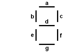
Your display controller should pass its 4 inputs to the 4-16 decoder you constructed, and the output of the decoder should be used to drive the seven LED signals
Each of the outputs can be represented as a boolean function of the four input variables. For example, if the input is 0101, then the output of the decoder should be a single 1 which turns on segments a, b, d, f, and g, while c and e are off, forming the digit "5" on the display.
You should implement all 16 hexadecimal digits (0 1 2 3 4 5 6 7 8 9 A b C d E F). Note that b and d are lower case to distinguish them from 8 and 0. You will find chapter 3.4 of the book and lecture 16 to be helpful.
Implementation
You should use the following plan for implementing this lab:- Draw out all the numbers on graph paper first.
- For each of the segments a–g, write down which numbers correspond to that segment.
- Build a 4-bit decoder as a subcircuit. You MUST have your decoder as a subcircuit in order to receive full credit for this lab. Documentation for how to create a subcircuit is here.
- For each segment, create one or more OR gates (as needed), add the appropriate outputs from the decoder to the OR gate.
- Keep wires straight or right-angle turns. Pick the order the decoder outputs will go into the OR gates so as to minimize wire crossing.
- If inadvertent connections are made, undo, don't try to fix it.
Performing step 2 before step 4 is critical. You don't want to be trying to wire this up while figuring out which decoder outputs you need to OR.
Submission
Make sure to select the "save online" button to save your project. This will make your project available to us for grading.C. Taylor, S. Checkoway